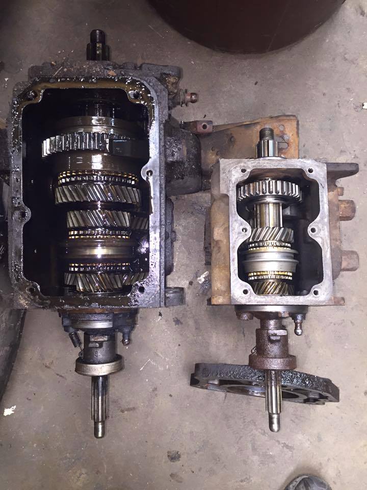
T98-A main shaft bushing is identical to the Jeep T18 main shaft bushing.
The bushing rides the inner seal face of seal that is pressed into the rear adapter plate.
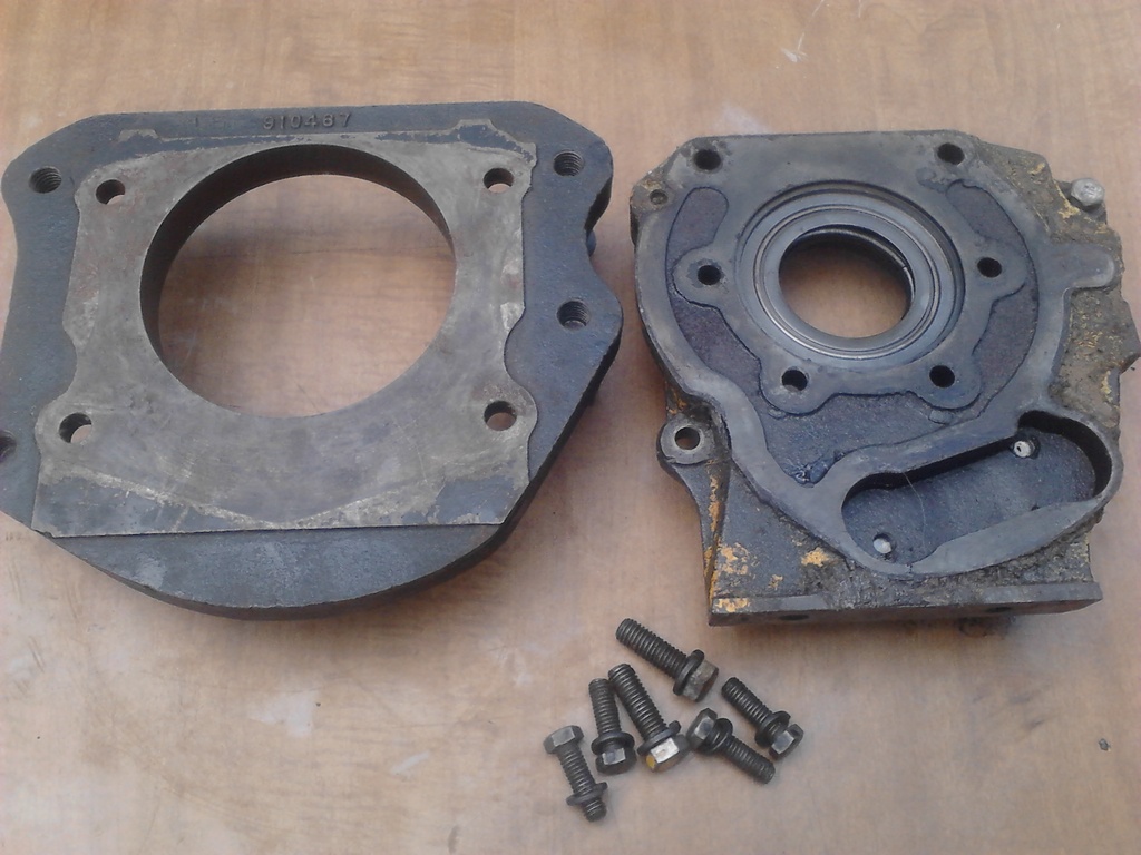
Oh so I guess that's my cue toward the rear adapter plate.
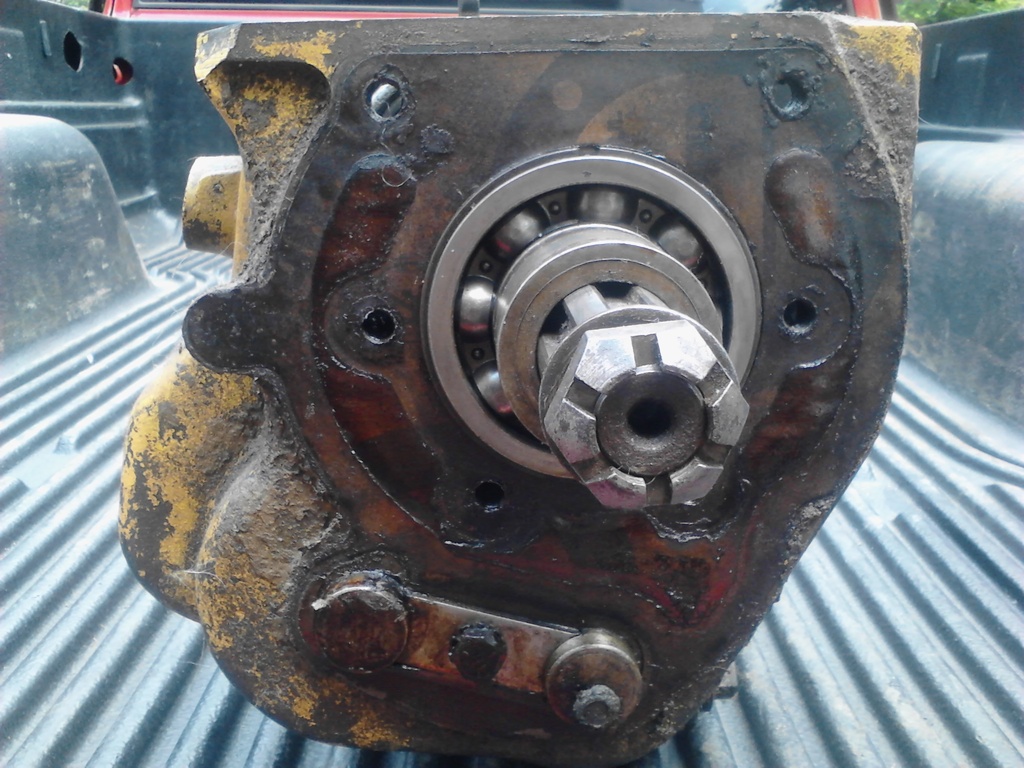
On your left you see the forward face of the bellhousing adapter plate which bolts to the Willys 134 bellhousing.
On your right you see the forward face of the Dana 18 adapter plate.
You can see the seal that rides the outside of the mainshaft bushing.
Both of these adapter plates are 7/8" thick.
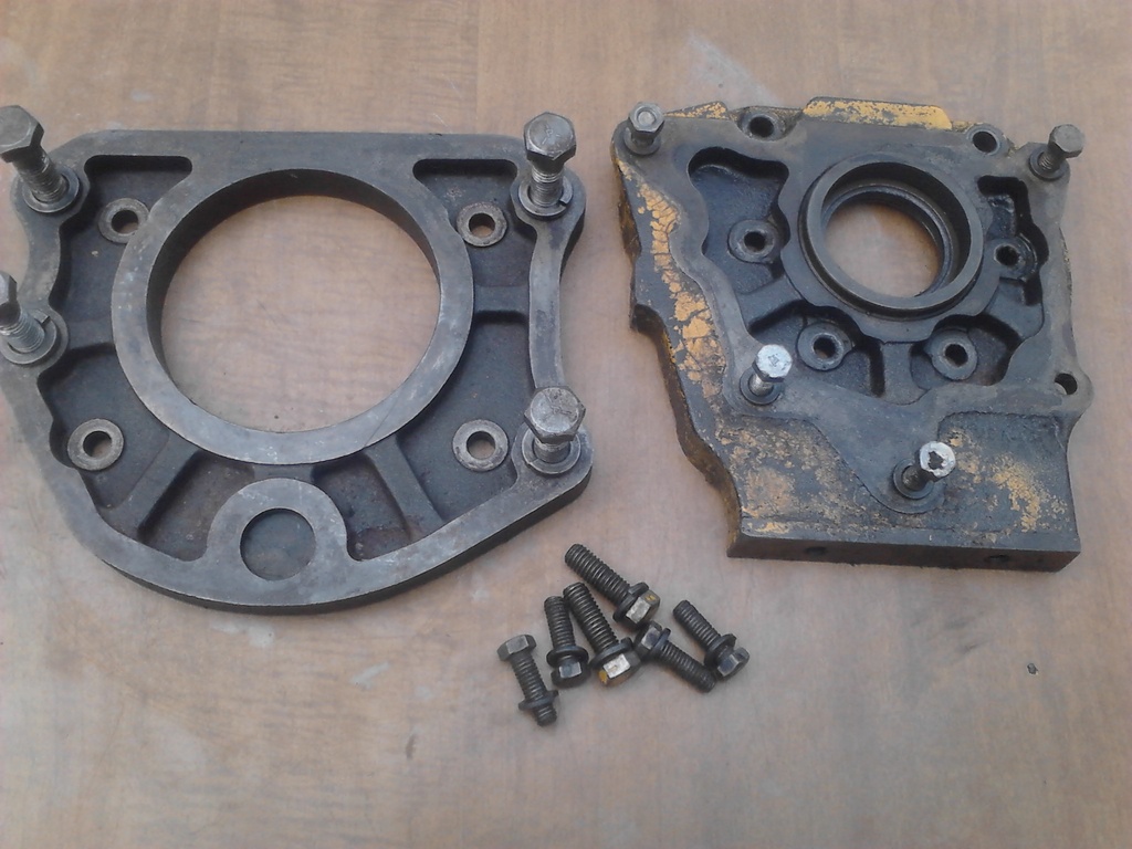
On your left you see the rearward face of the bellhousing adapter plate.
The 4 large bolts fit the T98 transmission pattern and the 4 bolt holes match the Willys 134 bellhousing.
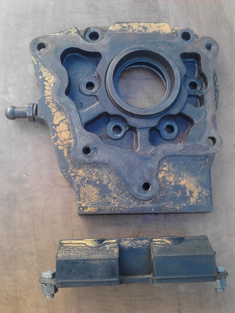
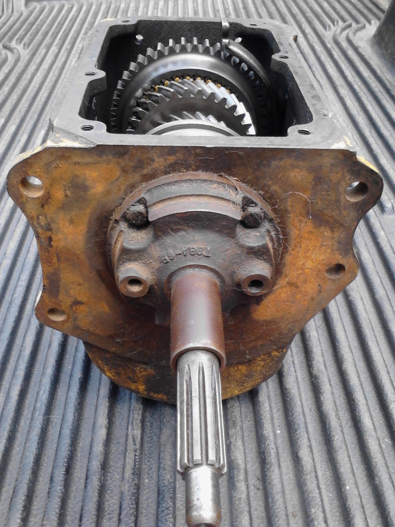
On your right you see the rearward face of the Dana 18 adapter plate.
You see the 6 bolts used to fasten the plate to the transmission and the usual 5 bolts required to attach the Dana 18 to the plate.
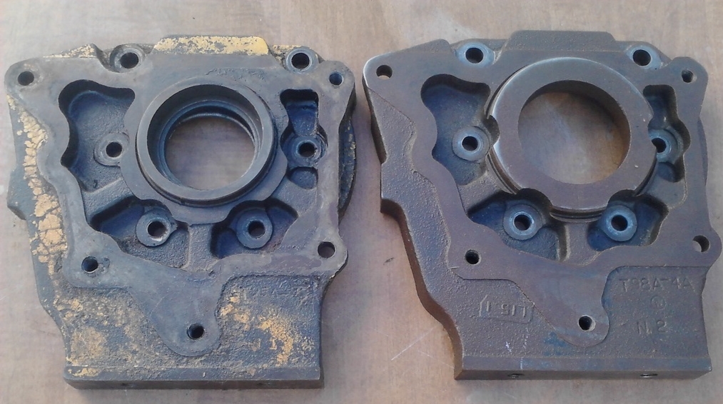
You can see how the rear is indexed into the transfer case via the protruding ring.
This ring is specific for small hole transfer cases (3-5/32" index bore)
Later Jeep T18 transmission adapter plates are identical except they have a 4" bore ring.
You can also see how the T18 adapter (on the right) is still marked as T98-A
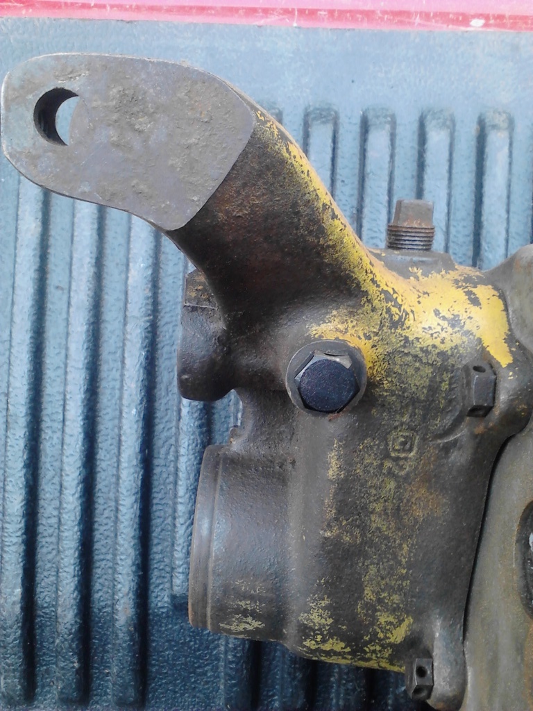
Jeep T98 and T18 clutch control ball pivot studs thread into the side of the rear adapter plate.
The T98 and T18 transmissions have no provision for mounting an insulator.
The rubber insulators mount at the flat narrow bottom of the rear adapter plate.The # 912721 insulators are not especially common but is still available new.
This pic shows the original 1956 insulator.
The later manufactured insulators may look slightly different
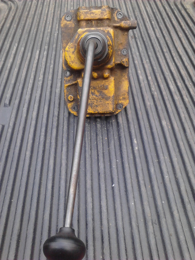
Here you see the top of the shift tower assembly.
Note that the 2 bosses seen extending out to the right side that are not used for CJ applications.Perhaps those could be used to mount an O.D. shift lever.
Also note that unlike later T18 shift towers there is no place for a reverse light switch.
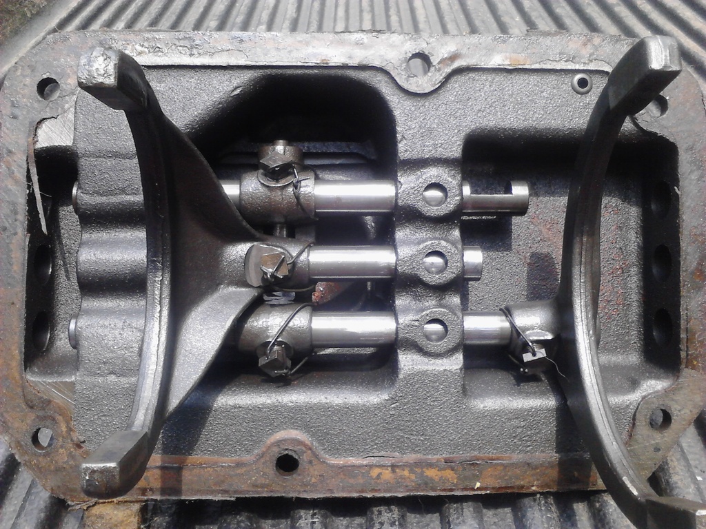
Here you see the working side of the shift tower assembly.
Note that whenever removing or installing any transmission shift tower, the transmissions gears and the forks should both be in neutral positions.
The large fork on your right fits into the 1st/reverse sliding gear.
Now note that the top rod has no shift fork.
That rod's "slot" fits onto the reverse shift lever as seen in the T-98 inside top view.
Also note how these early T98's were safety wired instead of having the later design allen head screws.
Finally note that the shift forks are of solid cast iron without the late type plasticized tips.
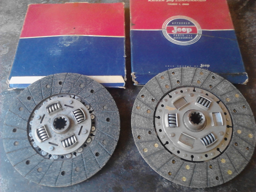
8-1/2" or 9-1/4" diameter Borg Beck driven disks will fit onto the 15/16" / ten spline main drive gear.
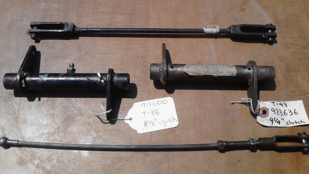
Here are 2 different clutch control "lever and tube" assemblies designed to fit T98-A with the above clutch sizes.
Note: I call them"lever and tube assemblies" because that was standard Willys terminology.Also, the pedal shaft release rod which measures 13-3/4", pin center to pin center.
Plus the special length release cable that is for use with the Willys T98-A.
The T 98-A release cable measures 13-5/8" OAL from ball end to threaded end.
The release fork itself and the release bearing carrier assembly are standard Willys parts.
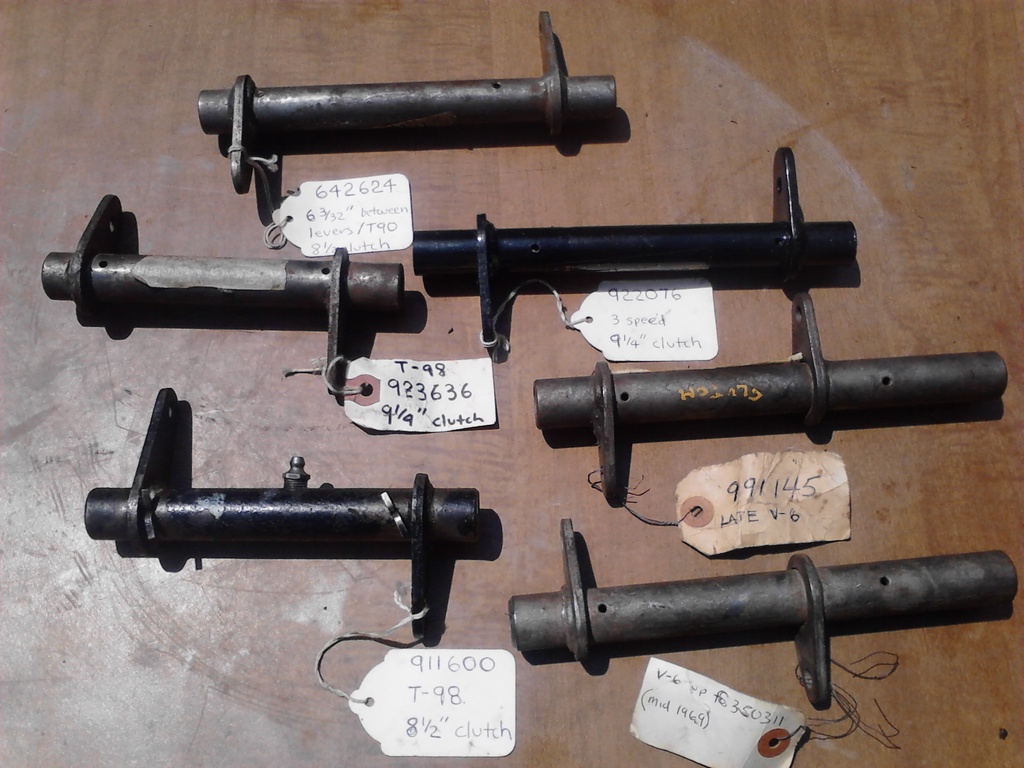
For a broader comparison here is the complete batch of early CJ clutch control "lever and tube assemblies" .
The combinations are determined by clutch make, clutch size and the transmission installed.
You see that the 2 used for T98-A installation require less width.
All CJ's used a tube that is 5/8" I.D. by 7/8" O.D.
The tubes 5/8" I.D. always fits over/onto the stud ball pivots.
Both of the T98-A lever and tube assemblies are 6-1/2" OAL (wide)
I measure each of these lever for throw length, from outside the 7/8" tube to the center of the clevis hole.
For 8-1/2" T98-A the pedal shaft lever throw length is 2".
The release fork lever throw length is 1-3/8".
Each lever is also be measured its position along the length of the tube.
I measure this from right end of tube to CL of each lever.
The pedal shaft lever is centered 1" from right end of tube.
The release fork lever is centered 5-1/2"" from right end of tube.
The levers are clocked toward specific locations.
I describe the lever clocking position as you observe the lever and tube assembly from the right side
(pedal haft lever is closest and release fork lever is farthest away).
The pedal shaft lever is clocked to 6 PM.
The release fork lever is clocked to 1 PM.
Transfer case for use with T98-A is same as all other 2.46 ratio post 1954 small hole cases with 2 exceptions.
The modified front bearing cap and the shorter shift pin.
Standard shift pin is 3-1/4" and T 98 shift pin s 3" long.
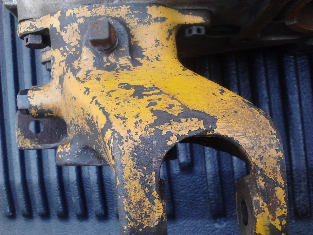
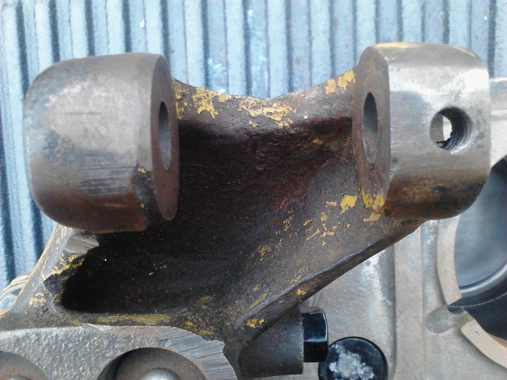
Here's the T 98 front bearing cap top view.
This part is identical to standard, except one side has been narrowed in order to clear the wider transmission.
From the factory about 1/4" width was removed on your right.
Side view shows how it was milled off:
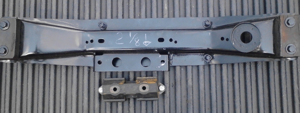
The transfer case itself sets upon a factory modified rear engine support cross member:
Here again you see where to locate the # 912721 Insulator.
2-1/8" represents relocation back from standard center of cross member
Note how T98 remains in same Right / Left position as T90 transmission.
You may also notice the two holes for standard parking cable clamp on your right.
Two additional holes were added on left side to accommodate the special longer parking cable.
Unlike the T90, the longer T98-A park cable goes to left side of transmission.
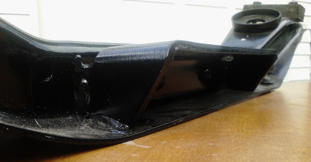
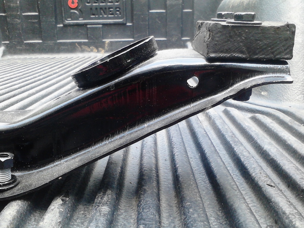
Here's another view of the T98 addition to the standard rear engine support cross member.
This extended platform sets about 1/8" below the original support height.
The T98-A cross member requires use of 1" inch thick oak spacer blocks and longer bolts.
You can see these blocks (unrestored condition) were factory painted black.
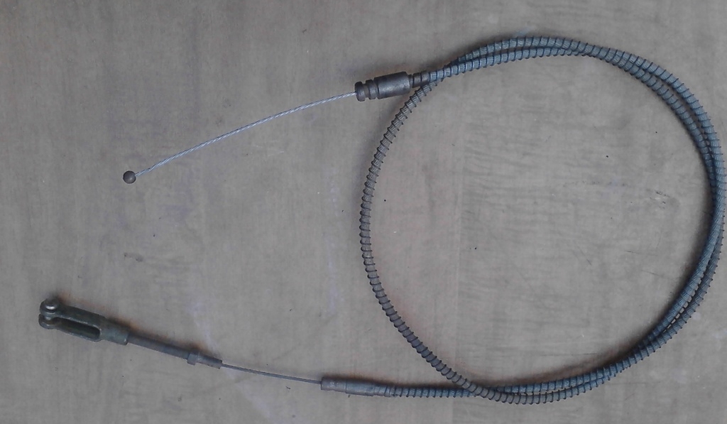
And now here's that original # 911693 Cable and conduit:
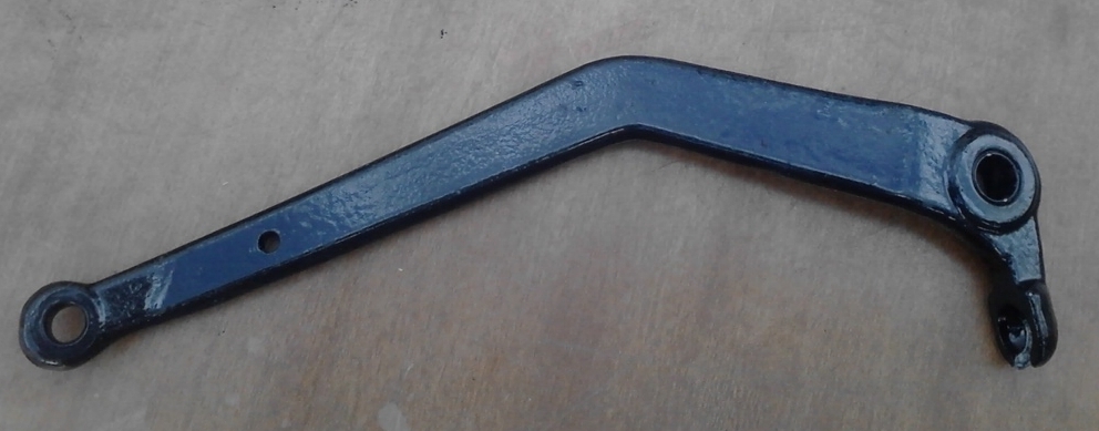
Note: Because this cable goes around the left side it requires that the transfer case park brake lever be of the late type (longer) design shown here:
In this pic you see the T98 shift levers (on your right) are nearly identical to standard levers .
The T98 transfer case levers are straight up down and not swept back like standard levers.
All other bends excepting rearward bends are identical.
This was done because the rear engine support cross member was moved aft on the frame exactly 5-1/2"
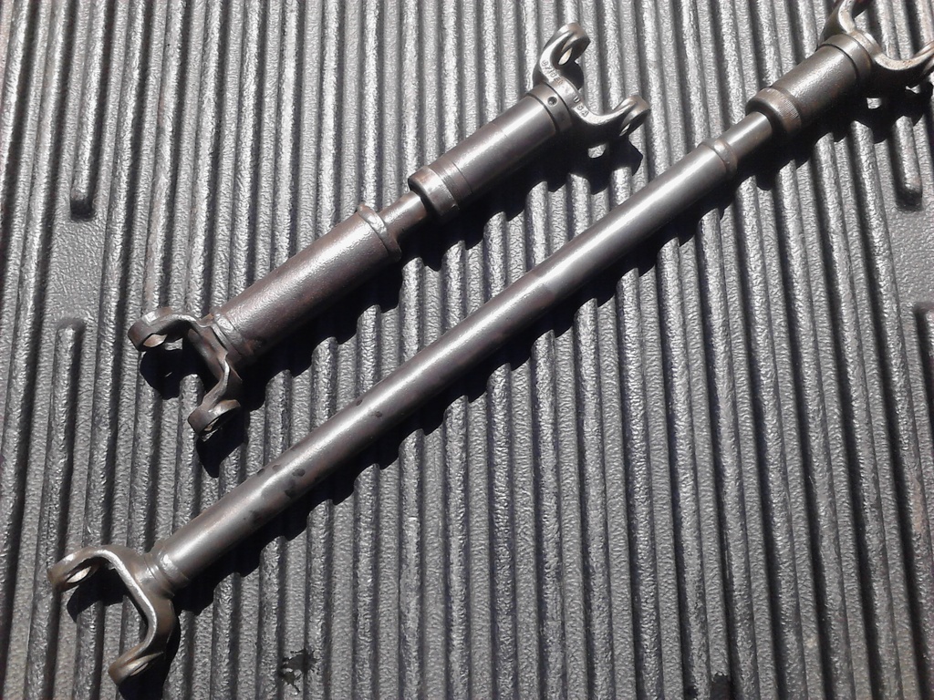
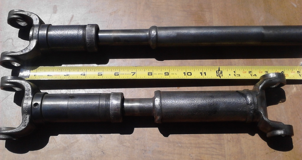
After installing transfer case its normally time for the propeller shafts.
The front measures 28" compressed and 29-1/2" extended.
The rear measures 13-1/8" compressed and 14-7/8" extended.
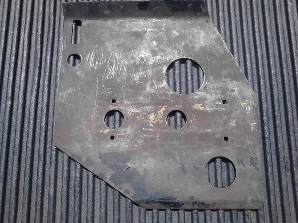
The skid plate was special formed for Jeeps having the optional T98-A.
The plate roughly measures 20-1/2" wide by 22" length.
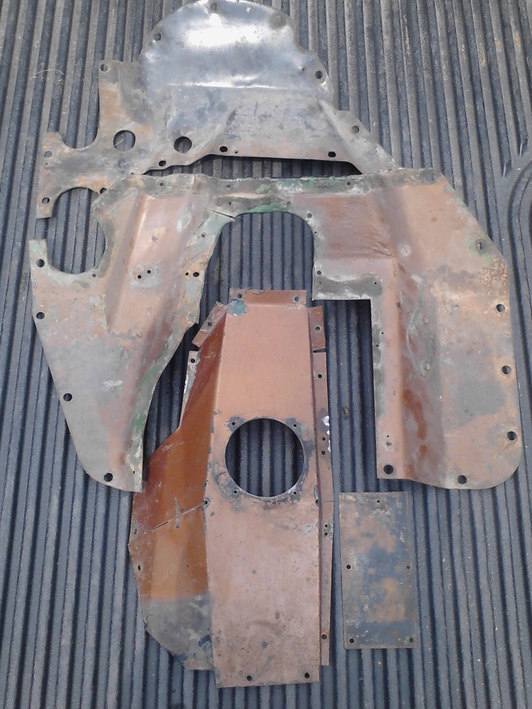
1956 CJ-5 or CJ-6 sheet metal for T98
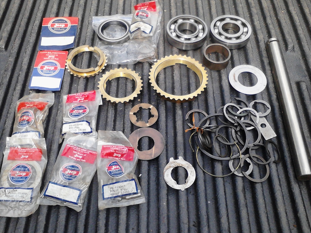
Here's the contents of a full T98-A rebuild kit direct to you from the late 1950's or the early 1960's.